Product Description

Title Line

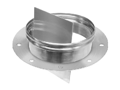
The Surge Hopper Spigot is available in Stainless Steel T304L and T316L and is custom-made with a 4mm outer flange (DIN or ANSI) and internally welded weir.   

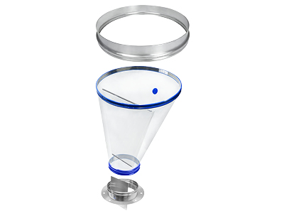
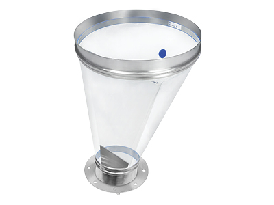
It is designed to fit with the Venting Surge Hopper to allow product flow down one side, and displaced airflow up and out the other to help prevent bridging.

The larger side/gap of the partition is where the product passes through.

Application
  • The Surge Hopper Spigot is designed to go on the small tapered end of a BFM® Venting Surge Hopper.

  • Ideal for use above rotary valves, or below a Bulk Bag Loading head.

  • The tail of the spigot and the internally welded weir can be easily cut down or cut on an angle to suit your existing pipework.


Key Features
tick for web-light blue-60x60px


Slightly tapered design to account for offset measurements

tick for web-light blue-60x60px


Available in two materials

Specifications

Title Line
Physical properties
Material/Fibre
Stainless Steel T304L, T316L
Construction/ Finish
≤ 0.8Ra micro-metres (32Ra micro-inches)
Wall Thickness (+/- 10%)
2.0mm / 5/64"
Certification and Compliance
FDA and USDA
Yes
3A Certified
Not yet assessed
EU Approved
Yes
Atex Certified
Yes
Dimensions
Available Diameters
Ø200mm (8”), Ø250mm (10”), Ø300mm (12”), Ø350mm (14”)

Tool Release- 300 x 200px

Product Option

Tool Release (TR)

Title Line

It is recommended that you add a Tool Release option to the Vented Surge Hopper Spigot.

To enable the installation of a TR (Tool Release) connector, a 6mm / 15/64” hole must be drilled in the top ridge of the head.

Getting Started with BFM® fittings

Title Line

We have Authorized Distributors who will help work through what you want to achieve and how BFM® fitting can improve your plant.

Tips and Guides

Title Line

For some useful technical tips and information get you started with selecting the BFM® fitting system.

Installation Process

Title Line
Helpful information for the entire installation process, from measuring up for the initial welding of your spigots to snap-fitting your connectors.

Contact Us

Title Line
If you would like to discuss your unique application, please contact us and we'll help find a solution for you.

Frequently Asked Questions

Title Line
What is the smallest gap a BFM® connector can fit into?

The smallest gap you can have between the BFM® spigots is 65mm (2.5") for an 80mm (3") long BFM® connector. Note that this gap may not be suitable for frequently changed connectors or for those with more than just a slight vibratory movement. Please also take some time to read the fitting instructions in the installation guides.

Can BFM® spigots be connected to aluminum pipes?

Because the stainless steel spigot will not directly weld to aluminium, another technique will need to be used, such as welding a flange to the spigot and then attaching by bolt or rivet to the pipe or using a Morris coupling to attach the spigot to the existing aluminium pipe.

Is it possible to get BFM® spigots manufactured in different thicknesses?

No - all of our spigots are manufactured with the same thickness of steel - 2mm. The 100mm BFM® spigots are sized to fit standard tube which is measured externally, all other BFM® spigot diameters are measured internally to accommodate nominal bore standard pipe.

Can we use Morris Couplings rather than welding the spigots to our pipework?

It is possible, however, Morris couplings need straight length equivalent to 1 1/2 times coupling length, so there would need to be enough space to fit this. You would want at least an inch of the spigot to remain to get enough clamping area.

I have a square pipe that I want to connect a BFM® to - what's the best way of doing this?

Square-to-round transition adaptations are easily achieved. Please contact us or speak to your local distributor for help.


How can I cut the Spigot to an exact imperial size?
BFM  spigots are manufactured to metric standards, with nominal diameters starting at 100mm (3 15/16 inches), and going up to
1,650mm (64 61/64 inches) in 50mm (1 31/32 inch) increments. z
 
This diameter is measured at the end of the tail of the spigots, and there is a very slight taper from the head to the base of the spigot meaning the head is actually around 6mm (15/64”) larger than the tail.

To obtain an exact Imperial Pipe Size for your spigot tail, simply cut the tail of the spigot to an appropriate length where the taper will be an Imperial equivalent measurement.