For applications where added safety is needed.
Upgrade the safety level of your Tool Release connectors by adding the TR Lock-Out Safety System to your Spigots.

Upgrade the safety level of your Tool Release connectors by adding the TR Lock-Out Safety System to your Spigots.
Our Tool Release (TR) connector range is a popular way to add a layer of safety to applications where the connector is mounted very close to equipment that is rotating or spinning very fast, such as above rotary valves or rotary knives.
If you are still concerned about staff improvising tools to gain access to the TR hole, the TR LOCK-OUT SAFETY SYSTEM is the ideal solution.

A simple addition of the TR Lock-Out tube creates an additional layer of safety to help reduce the possibility of staff accessing TR tool removal without approval.
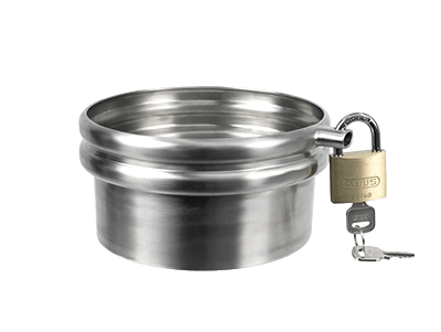
(Note: TR Lock Out System does not include the actual padlock)
View Specifications below for full details and restrictions.
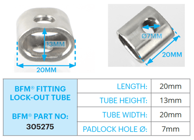
A ‘TR Lock-Out’ Tube is welded to the outside of the spigot over the TR (Tool Release) hole in the top ridge of the BFM® fitting Spigot.
A padlock is then inserted through the hole in the sides of the Lock-Out tube, making it impossible to insert anything through the TR hole without removing the padlock.
This means that only authorized staff who hold the key or combination to the padlock can gain access to the TR hole to insert a Tool Release tool to remove the Connector.
Watch our Technical Expert, Matt Bailey, explain in this quick product overview video:

To install the system, a TR Lock-Out Tube is welded over a TR hole (a standard or Smiley-Face hole) on the top ridge of the Spigot.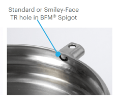
Extreme care must be taken when welding the Tube onto the Spigot to ensure no distortion of the top ridge of the Spigot occurs as this can affect the fit and seal of the BFM® fitting Connector.
We recommend the use of a heat-sink on the inside of the Spigot ridge during welding.