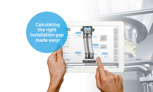
Correct Installation Gap (IG) Is Key
Whether you are installing a BFM® fitting system into a new process line or are retrofitting to replace an old-style connection, the most important part of the whole installation process is ensuring that the space between the two BFM® spigots (steel adaptors) is correct.
 This space is referred to as the Installation Gap (or IG) and will always be slightly shorter than the length of the connector to enable easy installation and removal. The IG also needs to account for any movement or offset involved at the point of installation.

Ensure you have watched the 'Measuring For Right Connector' video and have checked the correct IG for your application using the BFM® IG Calculator (available as a downloadable App.), which factors in variables like offset alignment or horizontal movement. Pipes and spigot lengths can be adjusted accordingly in the calculator to get the perfect fit for the space available for the installation.
See the section further down the page for some tips on the Welding Process for spigots.
Non-Direct-Welded Options with BFM® fittings
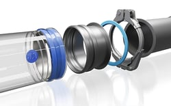 If you have a modular piping system that uses quick-release clamps, like Jacob tubing, this is the fastest installation option. BFM® fitting steel spigot adaptors are offered in a range of diameters with a pre-rolled 6mm lip that allows them to be instantly clamped onto an appropriate section of piping. This can effectively allow a BFM® fitting connection to be up and running in minutes.
 Another method is to pre-weld a BFM® fitting spigot adaptor to a ferrule or ANSI flange in the workshop before a shutdown so that there doesn’t need to be any in-situ welding undertaken. This will also help to speed up the installation process.
The most important aspect of either the direct-welded or non-direct-welded options is proper planning to ensure that the appropriate installation gap is observed when calculating the final positioning of the spigots to get the maximum performance from the BFM® fitting connector being used.
Connecting Non-circular Piping
(Square-to-Round Transitions)

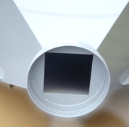
It’s not unusual to see non-circular inlets or outlets that need to be connected, and there are many examples of simple pipe adaptations, like square to round flanges that can be prefabricated to aid installation.
Product Flow Corrections
 If you have a particularly high-velocity product flow, or the product you are transporting is very abrasive, there are simple flow-correction modification plates that can be applied as part of your spigot installation to redirect the product away from the connector walls.
This will help increase the longevity of your flexible connectors. You can learn more about Flow Correction here.
Please contact your local Authorized BFM® Distributor if you need any assistance with the installation of your BFM® spigots.
%20(1)%20(2).webp "02-banner-industry looking_1300x600px (1) (1) (2)")