- ATEX category 3 - II 3D Ex tc IIIC T90°C Dc X, II 3G Ex nA IIC T4 Gc X
- Resistant to splashes and low-pressure jets of water from all directions

Know when your connectors are removed with this simple to install monitoring system, rated to IP65 level or ATEX certified.
Wherever you have a flexible connection in a live production system, if the connector is removed at any time, there is always a potential risk that hands can be placed near dangerous moving parts, such as rotary valves and rotating knives.
Now you can have added peace of mind that you can monitor when a BFM® fitting is removed in these areas.
The Pneumatic Monitoring System is designed to be used with BFM®'s Seeflex range of blue band connectors.
View Specifications below for full details and restrictions.
We have two available Pneumatic Monitoring System options, each with different compliance standards.


• Suitable for most operating environments
• Waterproof & dustproof

We have Authorized Distributors who will help work through what you want to achieve and how BFM® fitting can improve your plant.
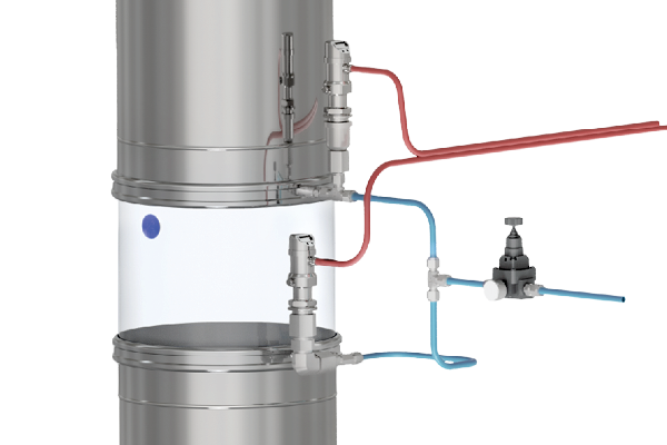
The system works by pumping pressurized air between the cuff of the BFM® blue band connector and the spigot.
Air-line sensors immediately detect if this outward pressure is released as the connector cuff begins to get pushed inwards anywhere around the connector when it is being removed, setting off an alarm and/or shutting off any moving parts below.
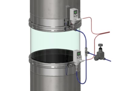
The control system can be arranged for multiple connectors to aid in monitoring larger installations.
Counters visibly show when the seal is not correct and the system can also be used as a positional sensor to ensure all connectors in a large plant are installed correctly at all times.
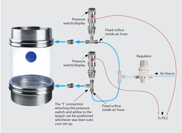
To install the system, a small hole (no larger than 3mm (7/64") in diameter) needs to be drilled in between the two ridges of each spigot. The spigot adaptors are then welded on and the system can be screwed in place and wired up to the appropriate control room system (Note: you will need to supply wiring and additional air-line & t-junctions as required). Download the installation guide.
Testing: We have tested a single Pneumatic Monitoring System on spigots up to Ø350mm. For spigots Ø400mm and over, we advise installing additional sensors. Please contact us for specific recommendations on this.


